
Current Topic: The OV7670 Camera Module is a synchronous device. Without additional hardware an Arduino can only transfer data asynchronously. the critical timing relationship of this method makes it a real challenge to acquire frames reliably from the camera and transfer them through any other interface for further processing.
Rumers that the OV7670 Is Arduino Compatible Are Highly Overrated.
In the loosest sense one could say that the OV7670 VGA camera module is Arduino compatible. As We will demonstrate. However. Because of the data transfer requirements, and the limited resources of an Arduino, the only useful imagery obtainable is from extremely slow moving frames. At a frame rate of about 0.225 frames/second (QVGA - 320 X 240) it is only useful for snapshots (of still images) or time lapse videos. And. Anything moving during the frame will blur the image.
For those of you considering using the OV7670 camera module don't fear. The camera itself actually works well, has a great image and some fine signal processing. It is also great in very low light levels and the color is remarkable in dim light. It is the Arduino that is the limiting factor here. Considering that the camera has a VGA (640 X 480) resoution, or 307,200 pixels, and two bytes per pixel that's almost 615,000 bytes/frame. Since the Arduino can only transfer 100,000 bytes/second there is a huge data bottleneck. In reality... In order to serve VGA at 30 frames per second would require an effective bandwidth of almost 10,000,000 bytes/second (10 MB/s). So Unfortunately... Anyone planning to use this method as a visual guidance system for their next robotic project are going to be completely disappointed.
None the less... With some circuit adjustment and some simple coding the camera can work and reliably provide frames over the serial (USB) port to a host PC for further processing.
What's The Best You Can Expect.
The major problem here is that the OV7670 is meant to be operated at a much higher clocking rate then is practical for the Arduino. Aside from the high data transfer requirement the Arduino (mega) only has 8192 bytes of RAM. In other words, only enough to buffer a few lines. The inability to cache a frame means that in order for this to work it must push the frame to external storage. In this case. An external computer (laptop). In real time.
The only way to practically achieve this is to provide a slower clock then is expected, to the OV7670, reduce frame-rate and disable clock-prescaling. This example used a 2.7 Mhz, primary, clock, to the Arduino (clone), which is way below the minimum recommended 10 Mhz. Furthermore, the clock prescapler was disabled and the clocking period was heavily divided. This resulted in frames that take 2 to 7 seconds to acquire. Unfortunately that's the best the Arduino is going to do naturally. Which means that anything moving during the frame capture will be blurred in the frame. It also means that the internal image processor (DSP) is running slower then the algorithms (coefficients) were designed for.
Even so... It still required some Assembly code for the actual frame capture. Honestly, the compiler did a pretty good job with the original C code however, the optimizing deferred certain operations (still logically correct) that extended the timing at the wrong places. Furthermore the relationship between the live data and the 'single-line' buffer and the serial transfer hardware and the frame/blanking period, needed closer connection to the hardware.
A bonus (benefit) of the tight assembly language programming was the additional ability to be able to write (update) configuration to the OV7670 during capture operations in the excess and predictable blanking period. A leftover (period) from analog tube technology. This allows live adjustment to color-balance, contrast, brightness, etc... During the capture. Only at a really slow rate. Really slow!
What did we get.
Using a program we wrote for Linux we acquired frames, in YUYV format, from the Arduino/OV7670 using the USB interface in UART mode and saved the raw data in a file. We further wrote a program to encode the raw frames, using the libvpx codec SDK, into VP_8 frames and encapsulated them in a Matroska container making them Webm compatible.
The first result is at 320 by 240 (QVGA) resolution and is over just over a thousand frames. It is encoded at a 'virtual' rate of five frames/second.
The Second result is full 640 by 480 (VGA) resolution and is over six hundred frames. It is encoded at a 'virtual' rate of five frames/second. Thus the actual time scale is one quarter the 320 by 240 time scale since it is actually four times greater in frame data size.
The final result was recorded in, mostly, dark (no light) conditions. For an additional reference internal and external lights are periodically used. It is recorded at 320 by 240 (QVGA) resolution and is just over one hundred fifty frames. It is encoded at a 'virtual' rate of five frames/second.
Connecting And Configuring The Hardware.
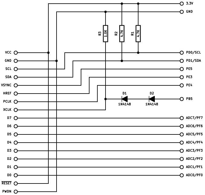
The camera module used required 3.3v power which was connected directly to the Arduino (clone) 3.3v power supply as was the ground (power return). Except for the master clock to the module all other signals are outputs which were also directly connected to the Arduino host. The main camera clock interface (from the Arduino to the module) needed to be reduced from 5v logic to 3.3v. To do this two 1N4148/1N914 type small-signal high-speed switching diodes were used in series to absorb (drop) the voltage differential and a resister to load the circuit (sink for the off/low state). Additionally the serial communication lines need to be terminated to the 3.3v supply voltage (pulled-up).
There was no breadboard available for this project so the components were attached directly to the OV7670 interface header. As was as the wiring to the Arduino. At the Arduino, the wires were soldered to header pins to plug into the sockets provided.


Although the circuit worked 'well' it turned out to not be perfectly reliable for long periods of time. The problem is probably due to the length of wires used between the two devices. Lots of care and attention was payed to the connections, at both ends, but mistakenly the wiring impedance was neglected. No wonder with 26 inches of wire all twisted about itself.
Writing The Software.
Asside from the standard Arduino OV7670 library the code for this project includes two parts. A frame-grab and serial hardware interface (driver), written in AVR assembly language and a companion interface application to aid in connection with a PC host (laptop) that does the actual image caching and processing.
//-----------------------------------------------------------------------------
// smegcam_7670.ino
//
//  OV7670->Arduino camera module demonstration.
//
// Copyright (c) 2015 - No Fun Farms A.K.A. www.smegware.com
//
//  All Smegware software is free; you can redistribute it and/or modify
//  it under the terms of the GNU General Public License as published by
//  the Free Software Foundation; either version 2 of the License, or
//  (at your option) any later version.
//
//  This software is distributed in the hope that it will be useful,
//  but WITHOUT ANY WARRANTY; without even the implied warranty of
//  MERCHANTABILITY or FITNESS FOR A PARTICULAR PURPOSE. See the
//  GNU General Public License for more details.
//
//-----------------------------------------------------------------------------
//
// History...
//
//   $Source$
//   $Author$
// $Revision$
//
// $Log$
//
//-----------------------------------------------------------------------------

#include <OV7670.h>
#include <FrameGrab.h>

//-----------------------------------------------------------------------------
// Local Definitions...

#define OV7670_XCLK 11
#define LED 13
#define MAXCONSOLE 80

enum _resolution { RES_VGA = 0, RES_QVGA, RES_QQVGA, RES_UNKNOWN };
enum _colorspace { CS_YUYV = 0, CS_RGB565, CS_BAYER, CS_UNKNOWN };

struct _res {
  enum _resolution res;
  const char *label;
};

struct _clrspc {
  enum _colorspace clrspc;
  const char *label;
};

//-----------------------------------------------------------------------------
// Local Variables...

static OV7670 cam(0x21);
static char console[MAXCONSOLE + 2];

static const _res resolution[] = {
  { RES_VGA,   "VGA"},
  { RES_QVGA,  "QVGA"},
  { RES_QQVGA, "QQVGA"}
};

static const uint8_t num_resolutions = sizeof(resolution) / sizeof(struct _res);

static const _clrspc colorspace[] = {
  { CS_YUYV,   "YUYV"},
  { CS_RGB565, "RGB565"},
  { CS_BAYER,  "BAYER"}
};

static const uint8_t num_colorspaces = sizeof(colorspace) / sizeof(struct _clrspc);

// Defaults.
static enum _resolution video_res   = RES_VGA;
static enum _colorspace color_space = CS_YUYV;
static uint16_t image_width         = 640;
static uint16_t image_height        = 480;

//-----------------------------------------------------------------------------
// Set OV7670 XCLK = clk/2 : 16Mhz clk = 8Mhz.

static void initializeIO(void)
{
  pinMode(LED, OUTPUT);
  pinMode(OV7670_XCLK, OUTPUT);
  TCCR1A = _BV(COM1A0) | _BV(WGM11) | _BV(WGM10);
  TCCR1B = _BV(WGM13) | _BV(WGM12) | _BV(CS10);
  TCNT1 = 0;
  TCNT1 = 0;
  //OCR1A = 0; //(F_CPU)/(2*(X+1)) ; 8.0000 Mhz. ; Doesn't work - Too Fast!
  OCR1A = 2; //(F_CPU)/(2*(X+1)) ; Maybe 2.6667 Mhz.
}

//-----------------------------------------------------------------------------

static void serial_get_line(void)
{
  int c;
  uint8_t i = 0;
  uint8_t parsing = 1;

  while(parsing)
  {
    while((c = Serial.read()) < 0);
    console[i] = c;
    if((i >= MAXCONSOLE) || (console[i] == '\n'))
    {
      parsing = 0;
      break;
    }
    i++;
  }
  console[i] = '\0';
}

//-----------------------------------------------------------------------------

static void get_config(void)
{
  uint8_t i;
  char r[16];
  char s[16];

  if(sscanf(console, "%s %s", r, s) == 2)
  {
    for(i = 0; i < num_resolutions; i++)
    {
      if(strncmp(resolution[i].label, r, strlen(resolution[i].label)) == 0)
      {
        video_res = resolution[i].res;
        break;
      }
    }
    for(i = 0; i < num_colorspaces; i++)
    {
      if((strncmp(colorspace[i].label, s, strlen(colorspace[i].label))) == 0)
      {
        color_space = colorspace[i].clrspc;
        break;
      }
    }
  }
}

//-----------------------------------------------------------------------------

void setup(void)
{
  Serial.begin(1000000);
  while(!Serial); // wait for Leonardo enumeration, others continue immediately
  Serial.print("Initializing Arduino I/O...\n");
  serial_get_line();
  // Setup PWM clock (XCLK) on pin 11.
  initializeIO();
  // Initialize Camera.
  cam.initialize();
  get_config();
  switch(video_res)
  {
    case RES_QQVGA:
      cam.setResolution(cam.QQVGA);
      cam.writeRegister(REG_CLKRC, 4);
      image_width = 160;
      image_height = 120;
      Serial.print(" Setting resolution 160 X 120 QQVGA.\n");
      break;

    case RES_QVGA:
      cam.setResolution(cam.QVGA);
      cam.writeRegister(REG_CLKRC,8);
      image_width = 320;
      image_height = 240;
      Serial.print(" Setting resolution 320 X 240 QVGA.\n");
      break;

    case RES_VGA:
    case RES_UNKNOWN:
    default:
      cam.setResolution(cam.VGA);
      cam.writeRegister(REG_CLKRC, 16);
      image_width = 640;
      image_height = 480;
      Serial.print(" Setting resolution 640 X 480 VGA.\n");
      break;
  }
  switch(color_space)
  {
    case CS_YUYV:
      cam.setColorSpace(cam. YUV422);
      Serial.print(" Setting color space YUYV (YUV422).\n");
      break;

    case CS_RGB565:
    case CS_BAYER:
    case CS_UNKNOWN:
    default:
      cam.setColorSpace(cam. RGB565);
      Serial.print(" Setting color space RGB565.\n");
      break;
  }
  Serial.write(0XFF); // Tell app to switch to binary data flow.
  Serial.println("");
  Serial.flush();
  cli(); // Disable interrupts... No time for them.
}

//-----------------------------------------------------------------------------

static uint8_t image_update[25];

void loop(void)
{
  ov7670_send_sync();
  ov7670_frame_grab(image_width * 2, image_height);
  // Only user interface.
  ov7670_toggle_led();
  // Get register update requests.
  ov7670_check_updates(image_update);
  // User feedback.
  ov7670_toggle_led();
}

//-----------------------------------------------------------------------------
// end: smegcam_7670.ino
And the Assembly language helper library.
;------------------------------------------------------------------------------
; FrameGrab.S
;
; Copyright (c) 2015 - No Fun Farms A.K.A. www.smegware.com
;
;  All Smegware software is free; you can redistribute it and/or modify
;  it under the terms of the GNU General Public License as published by
;  the Free Software Foundation; either version 2 of the License, or
;  (at your option) any later version.
;
;  This software is distributed in the hope that it will be useful,
;  but WITHOUT ANY WARRANTY; without even the implied warranty of
;  MERCHANTABILITY or FITNESS FOR A PARTICULAR PURPOSE. See the
;  GNU General Public License for more details.
;
;  OV7670->Arduino camera module demonstration optimized asynchronous frame
;   grabber for MEGA2560-R3 using connection configuration...
;
;   MNEMONIC OV7670 MEGA2560 FUNCTION
;       VCC      1      3V3   3.3 volt power
;       GND      2      GND   Power return (ground).
;       SCL      3       21   PD0/SCL
;       SDA      4       20   PD1/SDA
;     VSYNC      5        3   PE5
;      HREF      6        5   PE3
;      PCLK      7        2   PE4
;      XCLK      8        -   -
;        D7      9        7   ADC7/PF7
;        D6     10        6   ADC6/PF6
;        D5     11        5   ADC5/PF5
;        D4     12        4   ADC4/PF4
;        D3     13        3   ADC3/PF3
;        D2     14        2   ADC2/PF2
;        D1     15        1   ADC1/PF1
;        D0     16        0   ADC0/PF0
;
;  NOTE: This set of routines is meant to run exclusively with interrupts
;         disabled in order to provide proper acquisition of the cameras
;         synchronous interface.
;
;------------------------------------------------------------------------------
;
; History...
;
;   $Source$
;   $Author$
; $Revision$
;
; $Log$
;
;------------------------------------------------------------------------------

#define RZERO R1
#define TEMPL R18
#define TEMPH R19
#define PIXLL R20
#define PIXLH R21
#define VERTL R22
#define VERTH R23
#define HORZL R24
#define HORZH R25
#define UPDTL R24
#define UPDTH R25

#define REGXL R26
#define REGXH R27
#define REGYL R28
#define REGYH R29

#define REGX  REGXL
#define REGY  REGYL
#define TEMPR TEMPL

.equ REG_PINB,  0X03
.equ REG_PORTB, 0X05
.equ BIT_LED,   0X07
.equ MASK_LED,  0X80

.equ REG_PINE,  0x0C
.equ _VSYNC,    0x05
.equ _HREF,     0x03
.equ _PCLK,     0x04

.equ REG_PINF,  0X0F

.equ REG_UCSR0A,0XC0
.equ REG_UDR0,  0XC6
.equ BIT_UDRE0, 0X05
.equ BIT_RXC0,  0X07

;------------------------------------------------------------------------------
;
.lcomm .line_buffer,1284    ; Large enough buffer for 640 * 2/byte pixels +.

;------------------------------------------------------------------------------
;
.global ov7670_toggle_led
ov7670_toggle_led:
    LDI     TEMPR,MASK_LED      ; Load isolated LED bit.
    OUT     REG_PINB,TEMPR      ; Toggle Arduino MEGA GP LED.
    RET

;------------------------------------------------------------------------------
;
; Expected clocking sequence from OV7670 camera breakout module...
;       _____   ________________________________________________      ___   ___
; VSYNC      |_|                                                ------   |_|
;                  ___________     _             ___________     _
; HREF  __________|           ----- |___________|           ----- |___---------
;        _   _   _   _   _   _     _   _   _   _   _   _   _     _   _
; PCLK _| |_| |_| |_| |_| |_| ----- |_| |_| |_| |_| |_| |_| ----- |_| ---------
;
;------------------------------------------------------------------------------
;
.global ov7670_frame_grab
ov7670_frame_grab:
.save_registers:
    PUSH    REGXL               ; Save registers required
    PUSH    REGXH               ;  for re-entry back to the
    PUSH    REGYL               ;  C environment.
    PUSH    REGYH               ;
    MOVW    PIXLL,HORZL         ; Save Horizontal line (column) count.
frame_active:
    SBIC    REG_PINE,_VSYNC     ; Check frame state.
    RJMP    frame_active        ; Still in old frame.
frame_sync:
    SBIS    REG_PINE,_VSYNC     ; Check frame state.
    RJMP    frame_sync          ; New frame - Not sync yet.
parse_line:
    MOVW    HORZL,PIXLL         ; Get horizontal line count.
    LDI     REGXH,hi8(.line_buffer) ; Refresh line-buffer high (WORD).
    LDI     REGXL,lo8(.line_buffer) ; Refresh line-buffer low (WORD).
    MOVW    REGYL,REGXL         ; Input pointer = output pointer.
line_active:
    SBIC    REG_PINE,_HREF      ; Check line state.
    RJMP    line_active         ; Still old line.
line_sync:
    SBIS    REG_PINE,_HREF      ; Check line state..
    RJMP    line_sync           ; New line - Not sync yet.
pixel_sync:
    SBIS    REG_PINE,_PCLK      ; Check pixel state.
    RJMP    pixel_sync          ; Still old pixel.
parse_pixel:
    IN      TEMPR,REG_PINF      ; Get pixel data.
    ST      X+,TEMPR            ; Store pixel data in line buffer.
pixel_active:
    LDS     TEMPR,REG_UCSR0A    ; Get serial tx status.
    SBRS    TEMPR,BIT_UDRE0     ; Check tx-empty condition.
    RJMP    cache_pixel         ; Tx busy.
    LD      TEMPR,Y+            ; Get next cached pixel element.
    STS     REG_UDR0,TEMPR      ; Push pixel to serial controller.
cache_pixel:
    SBIC    REG_PINE,_PCLK      ; wait for PCLK pixel start.
    RJMP    cache_pixel         ; Still old pixel.
end_pixel:
    SBIW    HORZL,1             ; Decrement column count.
    BRNE    pixel_sync          ; Continue until line complete.
end_line:                       ; Push remaining pixels to serial output.
    CP      REGXL,REGYL         ; Check if all characters transmitted.
    CPC     REGXH,REGYH         ;  (word register).
    BREQ    next_line           ; Continue pushing cache until empty.
push_pixel:
    LDS     TEMPR,REG_UCSR0A    ; Volatile.
    SBRS    TEMPR,BIT_UDRE0     ; Check USC Data-Register-Empty condition.
    RJMP    push_pixel          ; Not ready yet.
    LD      TEMPR,Y+            ; Get next pixel element.
    STS     REG_UDR0,TEMPR      ; Transmit pixel element.
    RJMP    end_line            ; Continue.
next_line:
    SUBI    VERTL,1             ; Decrement row counter.
    SBC     VERTH,RZERO         ;  (word register).
    BRNE    parse_line          ; Continue parsing until done.
fg_return:
.restore_registers:
    POP     REGYH               ; Restore C environment.
    POP     REGYL               ;
    POP     REGXH               ;
    POP     REGXL               ;
    RET

;------------------------------------------------------------------------------
;
; Grab any parameter updates presumably during blanking period.
;
.global ov7670_check_updates
ov7670_check_updates:
    PUSH    REGXL               ; Save registers required
    PUSH    REGXH               ;  for re-entry back to C.
    MOVW    REGXL,UPDTL         ; Output buffer pointer.
    ST      X, RZERO            ; Flag.
    JMP     .ck_params
.push_param:
    LDS     TEMPH,REG_UDR0      ; Receive parameter.
    ST      X+,TEMPH            ; Push to buffer.
    ST      X, RZERO            ; Termination.
.ck_params:
    LDI     TEMPL,0X40          ; Time out.
.wt_param:
    LDS     TEMPH,REG_UCSR0A
    SBRC    TEMPH,BIT_RXC0
    JMP     .push_param
    DEC     TEMPL
    BRNE    .wt_param
cu_return:
    POP     REGXH               ;
    POP     REGXL               ;
    RET

;------------------------------------------------------------------------------
;
xmit_digit:
.xmit_busy:
    LDS     TEMPH,REG_UCSR0A
    SBRS    TEMPH,BIT_UDRE0
    RJMP    .xmit_busy
    STS     REG_UDR0,TEMPL      ; Transmit pixel element.
    RET

;------------------------------------------------------------------------------
;
.global ov7670_send_sync
ov7670_send_sync:
    LDI     TEMPL,0X00
    CALL    xmit_digit
    LDI     TEMPL,0X00
    CALL    xmit_digit
    LDI     TEMPL,0XFF
    CALL    xmit_digit
    LDI     TEMPL,0XAA
    CALL    xmit_digit
    LDI     TEMPL,0X55
    CALL    xmit_digit
    LDI     TEMPL,0X00
    CALL    xmit_digit
    RET

;------------------------------------------------------------------------------
; end:FrameGrab.S
Conclusion.
The only thing the Arduino (AVR) series of controllers is really sutable for is configuring and controlling the OV7670 Camera Module. It is really not capable of pumping the kind of data the camera requires to operate properly.
Oh well!
Additional Resources That May Be Useful...
23594


